

Tips & Tricks
Tips&Tricks
On this page one can find additional help for installation and tips or FAQ’s
6 Volt 3 brush Generator:
The 6 Volt generator is self powering/energising. The remnant magnetism builds up the voltage in the generator without the need of a battery.
A 6 Volt generator does not need much attention. It works flawless for many years.
The 6 Volt generator delivers about 9-10 amps maximum. The voltage is not really regulated. Due to the design of the generator the balanced load (lamps and Coil) and the presence of the battery, the Voltage is more or less controlled.
When the old cut-out Relay is being replaced by the solid state(6Volt relay) one, it should work right away. Assuming the old electrical system worked without problems.
If it is unknown if the generator works, or if the electrical wiring is correct, problems can show up. Be aware that all our regulators and relays have been tested for functionality after production.
Common seen errors:
Generator is not working due to:
- faulty armature
- faulty windings
- short circuit in the third brush
- short in the paper insulation inside the generator
- field coils mounted reverse
- not polarized correctly
- Main switch wired wrongly
- Battery mounted reverse!
- Wiring faulty
Please refer to the repair manual or workshop manual for repair and testing of the generator.
The 6 Volt generator (3 brush) only works with the 74750-38 ;old nr. 4785-38 model cut-out relay. Our replacement for these old cut-out is the 6 Volt solid state Relay as shown below in the figure.
This Relay is on the market for almost 15 years, not showing any problems.
12 Volt Electronic regulator
This regulator works only with the two brush type generators. It will not work on the 3 brush generator!
Since the principle of the two brush 12 Volt generator is the same as the 6 Volt, it can happen that the generator does not deliver output. The generator is self energising and should produce power when running.
Most comment problem with these type of generators is the polarity of the remnant magnetism. After a repair, one can have interchanged the poles, so the polarity of the field is wrong. This can be corrected easily by flashing the generator. This is described in the installation instructions of this regulator, and can also be downloaded from this site.
Be very careful if the generator has the wrong polarity! It means the generator’s output is negative! In the electronic regulator, a special circuit protects the electronics from being damaged, but is not capable of absorbing all energy, especially when throttling the engine. If the dashboard generator light does not go off when engine speeds is just above idle, then the generator is most likely negative polarized!
Higher engine speeds ruins the regulator! Be very careful!
Common seen other errors:
- Field coils wrong mounted/ wired or short to housing
- Battery mounted reverse!
- bad ground
- wiring wrong
- Interchanged poles
- new poles mounted
The Electronic regulator needs a proper ground made, made though the mounting flange. Be sure both metal surfaces are clean, so proper contact is made.
With a simple Voltage tester (analogue or digital) one can test if the output of the generator is positive (ok) or negative (not ok)
Put the negative (black) test lead to ground, and connect the positive (red) lead to the generator pole which states: A (armature)
Run the engine at idle speed.
The Voltage must indicate a positive voltage. If not, the generator needs to be flashed.
Electronic Ignition
What to check if the electronic Ignition does not work as expected
Be sure the system works with normal points.
Check again the installation instructions
The ignition timing must be checked and adjusted after installing the Ignition Module! The ignition module works identical to the points:
Points closed (red LED is on) coil is beeing charged.
Points just open (red LED goes off) coil releases energy, thus generating a spark.
Simple test with a voltmeter or DVM (digital volt meter)
Connect the meter to the red wire of the ignition where it is connected to the coil. Crank the engine until the red light is on (coil =charged) Readout must be near the voltage of the Battery.
If much lower (>1 Volt), somewhere in the electrical system resistance is in play.
e.g.one has a very weak battery. (or mainswitch; wiring harnass, lugs)
Connect the DVM/ meter r to the black wire of the ignition where it is connected to the coil. Red light is still on. Readout must be less than 1 Volt.
If higher, the ignition housing, timer base or ground wire is not proper grounded. Check for rust, painting etc.
The ignition module will fit many types of ignition bases. If one feels he has to adjust the holes in the ignition system for fit, it is for sure not designed to work on that timer base. Please recheck make/model of timer base. Do not adjust the Ignition Module.
Coil: Check coil type for right operating voltage.
Be sure the spark cables are propperly attached to the coil. This can be checked using an Ohm meter.
Main switch in off position!Choose the Ohmic range and measure between the spark cables the resistance. One should find a value of approx. 10-20 kOhm.
If open, the cables are not attached to the coil, or the coil is broken (open loop)
Some users strip the spark cables and squeeze them in the coil. DO NOT DO THAT!!
The risk is that the spark finds a short way inside the coil, preventing a good spark at the spark plugs, or even none at all.
Resulting in a engine with just one cylinder working, or even none.
Just cut them traight, and press them over the accepting pins of the coil. One can prepare a hole axial to the copper core of the cable. The pin in the coil will find his way easier by doing this.
Different style of ignition base:
Early model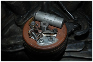
1947 model only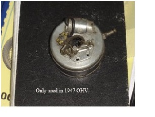
Late style base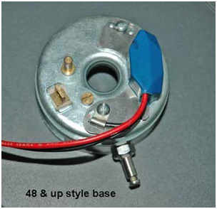
Please check which type of base is fitted on your bike. The year of the bike can differ from the model of the ignition base which should be mounted. This due to the long history and restorations of a bike.
Kit 36-47 is reselled with order number 0156900 36-47
Kit 48-64 is reselled with order number 0156903 48-64
Warrenty: No warrenty is applicable if a problem occures in the battery load system. In case the battery disconnects from the circuit/wiring while engine running at high speed and thus loading the battery, a high energy dump takes place in the wiring. (e.g.broken wire or blown fuse) In situations where this occurs, the Ignition module will fail due to high energy peaks caused by the moment of disconnect.
E.g. a 6 Volt system generates a steady 30 Volts output on high RPM if no battery is connected. The Bulbs will blow; same for the Ignition module.
Also in the battery a internal mechanical failure can occur. Not visible to the eye, and is difficult to detect.